
The Problem: Making PCBs That Mount Like Components
Sometimes you need a PCB that functions as a component—a module that solders directly onto a host board. Standard PCB edges are bare laminate, with no solderable surface. You could add a connector, but that adds cost, height, and potential failure points.
The solution is castellated holes: plated half-holes at the board edge that provide solderable contact points, allowing one PCB to mount directly onto another.
What Are Castellated Holes?
Castellated holes are formed by drilling plated through-holes at the board edge, then routing through them to create half-moon shaped contacts. The name comes from castle battlements—the grooved pattern resembles medieval fortifications.

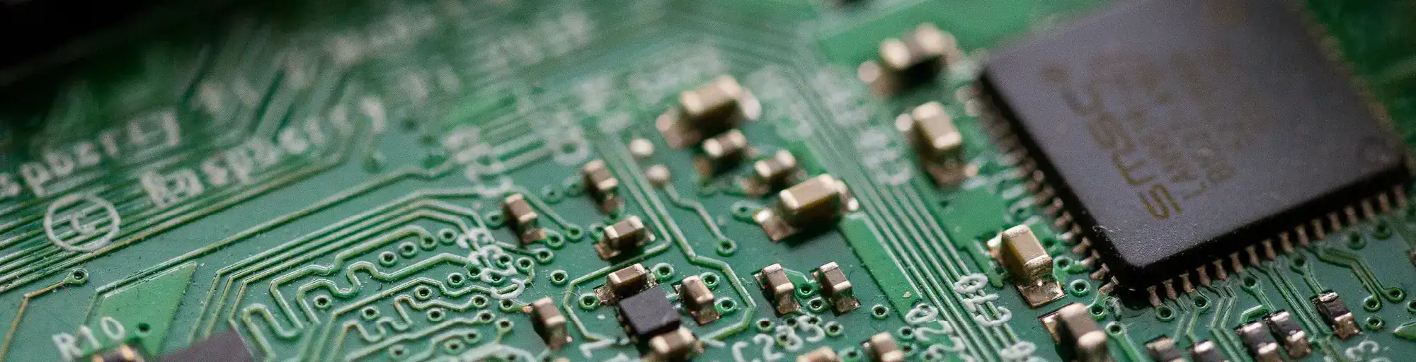
Planar transformer module with castellated holes for direct board-to-board soldering
How Castellation Works
The process requires careful sequencing:
- Drill – Full plated through-holes are drilled at the intended edge locations
- Plate – Holes are copper-plated like standard PTH vias
- Route – The board outline is cut through the centre of the holes, leaving half-cylinders of plated copper at the edge
Castellation is typically applied to specific areas rather than the entire board perimeter. Tabs are needed to hold panels during wet processing—you can’t plate an edge that’s already been cut.
Applications
Wireless Modules
Bluetooth, WiFi, and cellular modules commonly use castellated mounting. The module manufacturer can fully test the PCB, then customers solder it as a single component.
Daughter Boards
Castellated edges allow vertical or horizontal mounting of small boards without connectors.
Planar Transformers
PCB-based transformers use castellations to connect primary and secondary windings across stacked boards.
Test Fixtures
Castellated boards can plug into pogo-pin test fixtures for production testing.
Design Considerations
Hole Size and Pitch
- Minimum hole diameter: 0.6 mm (finished)
- Minimum pitch: 1.0 mm (edge-to-edge spacing depends on hole size)
- Copper thickness: Standard PTH plating (typically 20–25 µm minimum)
Board Thickness
Thinner boards (0.4–0.8 mm) are common for castellated modules to minimise the height added to the host assembly.
Surface Finish
ENIG is preferred for castellated contacts—flat surface, good shelf life, and reliable soldering. HASL can leave uneven surfaces in the half-holes.
Manufacturing Limits
We regularly produce castellated boards as small as 5×5 mm in 0.4 mm thick FR-4. Smaller is possible but discuss with us first—handling and panelisation become challenging at very small sizes.
Related Articles
- Embedded Transformers in PCBs – Planar transformer modules using castellated mounting
- How Multilayer PCBs Are Made – Understanding the plating and routing process
- Multilayer PCB Capabilities – Edge plating specifications
Need castellated PCBs for your module design? Request a quote – we manufacture boards as small as 5×5 mm with castellated edges.