
Archive Note: Embedded resistor technology is technically mature and used in production, particularly in military, aerospace, and high-reliability applications. However, the number of PCB manufacturers offering this capability remains limited, and finding qualified suppliers requires lead time. This article explains the technology for educational purposes.
The Problem: Termination Resistors Everywhere
High-speed designs require termination resistors at the end of every controlled impedance trace. In a dense design with hundreds of nets, that means hundreds of small resistors, each consuming board space, adding assembly cost, and creating potential failure points.
Embedded resistors integrate these passives directly into the PCB, eliminating surface-mount components without sacrificing functionality.
How Embedded Resistors Work
There are two main approaches:
Resistive Foil (Ohmega-Ply)
A thin nickel-phosphorus alloy layer is bonded to copper foil before lamination. During PCB fabrication, the copper is etched to define the resistor geometry, leaving the resistive layer to form the actual resistance.
The resistance depends on:
- Sheet resistivity - material property, measured in Ω/square
- Geometry - length and width of the resistive element
Formula: R = (L/W) × Rₛ
Where:
- R = Resistance (ohms)
- L = Length of resistor element
- W = Width of resistor element
- Rₛ = Sheet resistivity (Ω/square)
Carbon Ink (Screen Printed)
Carbon-loaded polymer ink is screen printed onto inner or outer layers. This is an older technology, lower precision, but also lower cost.
Ohmega-Ply Specifications
Ohmega-Ply is available in several sheet resistivities:
| Sheet Resistivity | Typical Applications |
|---|---|
| 25 Ω/square | Low-value resistors, bus termination |
| 50 Ω/square | General purpose |
| 100 Ω/square | Most common, good range of values |
| 250 Ω/square | Higher value resistors |
More information: Ohmega Technologies
Calculation Example
Given:
- Sheet resistivity: 100 Ω/square
- Required resistance: 500 Ω
Calculation:
- Squares needed: 500 ÷ 100 = 5 squares
- If trace width is 0.4 mm (16 mil), length = 5 × 0.4 mm = 2.0 mm (80 mil)
Verification: R = (2.0/0.4) × 100 = 500 Ω ✓
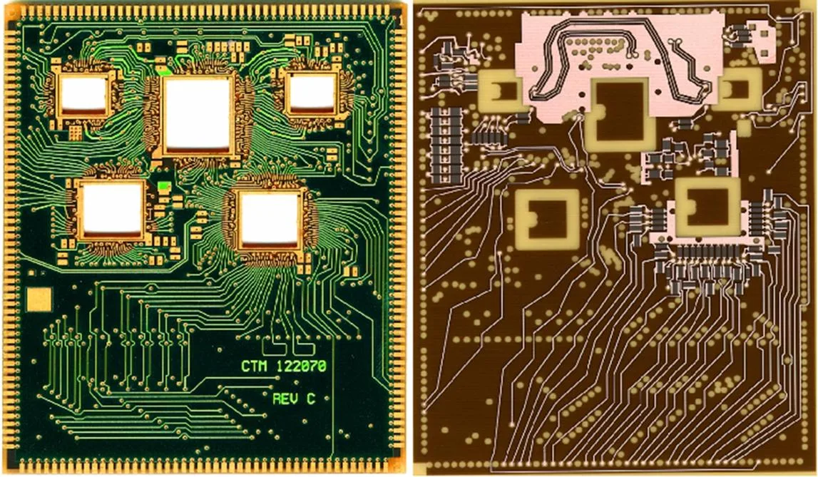
PCB with embedded resistors: complex routing with Ohmega-Ply resistive elements on inner layers
Carbon Ink Option
For lower-precision applications, carbon paste offers a simpler alternative:
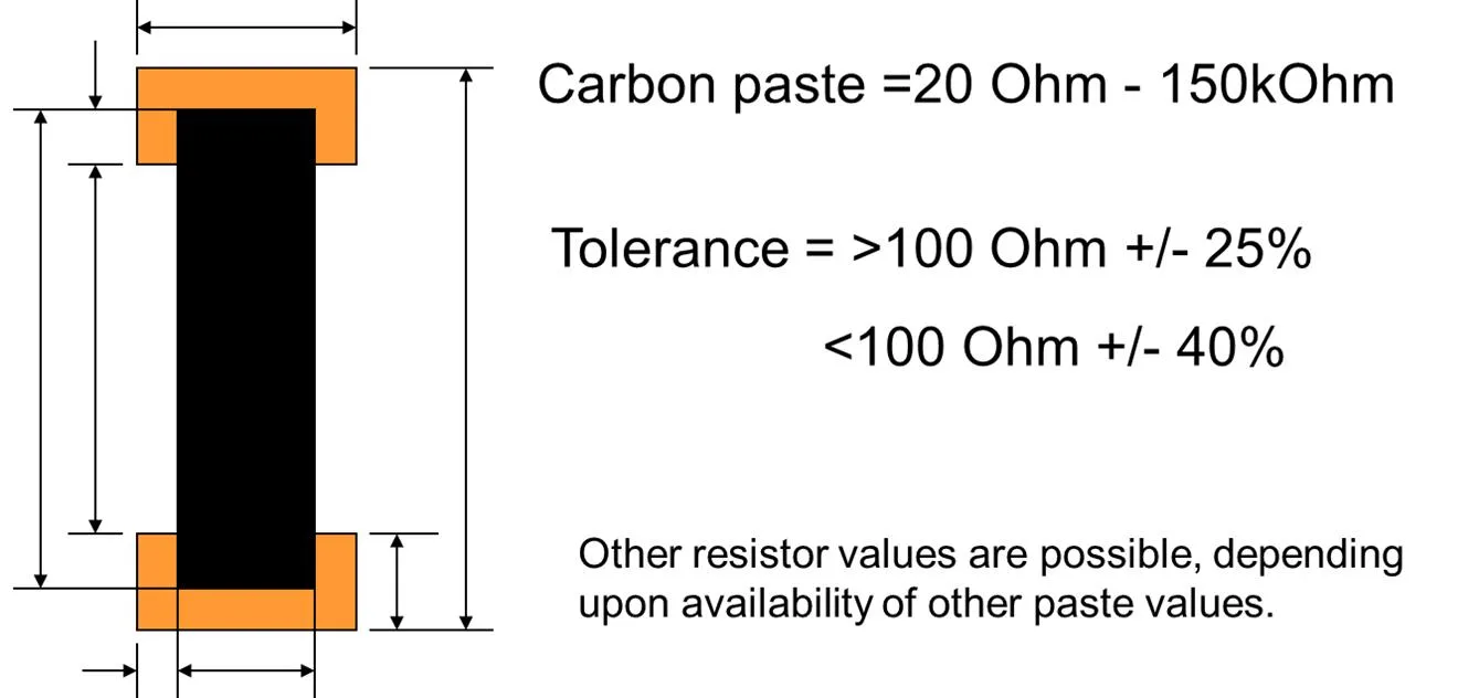
Carbon paste resistor geometry: resistance determined by length-to-width ratio
Carbon paste specifications:
- Resistance range: 20 Ω – 150 kΩ
- Tolerance: ±25% (>100 Ω), ±40% (<100 Ω)
- Other values possible depending on paste availability
Carbon ink is screen printed and cured. It’s commonly used for:
- Membrane switches
- Keypad contacts
- Low-precision termination
- Cost-sensitive applications
Tolerances
| Method | Standard Tolerance | With Laser Trimming |
|---|---|---|
| Ohmega-Ply | ±10–15% | ±1% |
| Carbon ink | ±20–30% | ±5–10% |
Laser trimming measures each resistor and cuts a precise trim path to dial in the exact value. This adds cost but enables tight tolerances regardless of initial material variation.
Design Considerations
Keep It Simple
Embedded resistors work best for:
- Fixed values that won’t change
- Moderate tolerance requirements
- High quantities where assembly savings matter
Temperature Coefficient
Embedded resistors have temperature coefficients (TCR) that affect precision applications. Ohmega-Ply TCR is typically ±100 ppm/°C, acceptable for termination but not precision measurement.
Power Handling
Maximum power depends on thermal dissipation. Rule of thumb: 50–100 mW per resistor for buried elements, more for surface-exposed resistors with good thermal path.
Layer Placement
Embedded resistors are typically placed on inner layers close to the surface (layer 2 or n-1). This simplifies the stackup while keeping resistors accessible for trimming if needed.
When to Use Embedded Resistors
This technology makes sense when:
- You have many resistors of the same or similar values (termination networks)
- Board space is constrained
- High reliability is required (no solder joints to fail)
- The design is stable and resistor values won’t change
- Volume justifies the NRE for resistive foil material
Industry Status
Embedded resistor technology using Ohmega-Ply or similar materials is more established than embedded active components, but supplier availability remains limited. Military and aerospace applications use embedded resistors in production, but commercial adoption has been slow due to:
- Higher upfront costs compared to discrete SMT resistors
- Limited PCB supplier base with qualified processes
- Design inflexibility once values are committed to artwork
Related Articles
- Embedded Capacitors in PCBs - Forming capacitors within PCB layers
- Embedded Components Overview - Active component embedding technology
- PCB Materials and Laminates Guide - Material selection for embedded designs
Questions?
If you’re evaluating embedded resistors for a specific application, contact us. We can discuss the technology and help you understand whether it makes sense for your requirements.