
The Problem: Wire-Wound Transformers Limit Power Density
Traditional wire-wound transformers are bulky, expensive to manufacture, and difficult to integrate with modern surface-mount assembly. In power supplies where size matters—think portable devices, distributed power, and space-constrained applications—conventional magnetics become the limiting factor.
Planar transformers solve this by etching the windings directly into PCB layers, creating flat, repeatable, easily assembled magnetic components.
How Planar Transformers Work
Instead of wire wound around a bobbin, planar transformers use spiral traces on PCB layers as windings. A ferrite core (typically an E-core or ER-core) clamps around the PCB, completing the magnetic circuit.
Key differences from wire-wound:
- Windings are photolithographically defined—perfectly repeatable
- Very low profile (determined by ferrite core height)
- Excellent thermal characteristics (copper spread across PCB area)
- Interleaving of primary and secondary is easy (just stack layers)
- 100% compatible with surface-mount assembly
Advantages
High Efficiency
Planar transformers routinely achieve 94% efficiency or higher. The flat, wide conductors have lower AC resistance at high frequencies than round wire.
Low Profile
With the right core selection, total height can be under 10 mm—often 5–6 mm for lower power designs.
Excellent Repeatability
Every transformer is identical because the windings are defined by PCB artwork. No hand-winding variation.
Low Noise
The tight coupling between layers and controlled geometry results in lower leakage inductance and reduced EMI compared to wire-wound designs.
Integrated Design
The transformer can be part of the main PCB (windings on inner layers) or a separate module that mounts like any SMT component.
Typical Specifications
| Parameter | Typical Range |
|---|---|
| Power | 5 W – 500 W |
| Efficiency | 90–96% |
| Operating frequency | 50 kHz – 2 MHz |
| Isolation voltage | 500 V – 4 kV (depends on stackup) |
| Profile height | 4–15 mm |
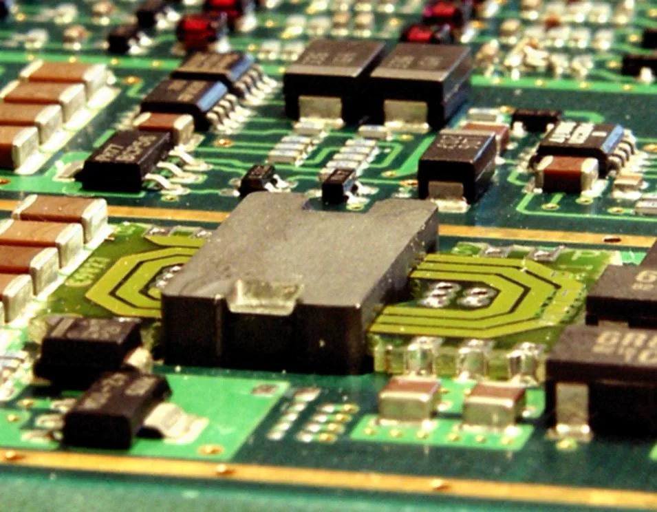
Planar DC/DC converter: 150 W, 94% efficiency, 100% surface mounted
Design Approaches
Integrated Windings
The transformer windings are etched on inner layers of the main PCB. The ferrite core mounts on top. This minimises parts count but constrains the main PCB stackup.
Separate Module
A dedicated transformer PCB with castellated holes or standard SMT pads. The module is assembled separately, tested, then soldered to the main board like any component.
Advantages of separate module:
- Transformer can be fully tested before assembly
- Main PCB stackup is not constrained
- Ferrite assembly happens offline
- Easier to second-source or redesign independently
Layer Count Considerations
The number of PCB layers depends on:
- Turns ratio – more turns = more layers
- Current capacity – parallel layers for high current
- Isolation requirements – dedicated isolation layers may be needed
A simple 1:1 transformer might need only 4 layers. A complex multi-output design could require 12 or more.
When to Consider Planar Transformers
This technology makes sense when:
- Height is constrained – planar designs are significantly flatter than wire-wound
- Repeatability matters – production volumes benefit from photolithographic consistency
- High frequency operation – planar windings have lower AC resistance
- EMI is critical – controlled geometry reduces leakage inductance
- Surface-mount assembly is required – no hand-winding or through-hole insertion
Suppliers
You can design planar transformers in-house or source from specialists:
- Payton Planar (US)
- Standex-Meder Electronics (EU/US)
- Coilcraft (standard modules)
- Custom designs from any PCB-capable transformer manufacturer
Related Articles
- How Multilayer PCBs Are Made – Fabrication process for multilayer designs
- Castellated Holes and Edge Plating – Mounting options for PCB modules
- PCB Materials and Laminates Guide – Material selection for power applications
Interested in planar transformer PCBs? Contact us to discuss your power conversion requirements.